
Contrôle
Une parfaite connaissance de l'état de votre installation et une maitrise de son fonctionnement.

Sécurité
Soyez averti en cas d'anomalie et paramétrez vos alertes personnalisées.

Longévité
Conservez vos équipements dans leur plage de fonctionnement optimale.

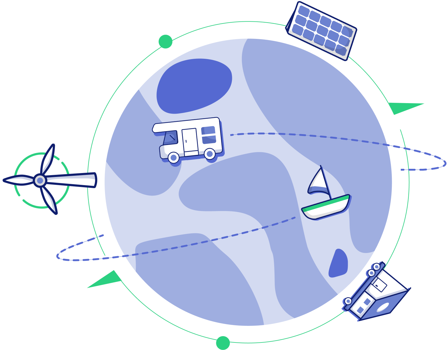
Autonomie
Une gestion de la charge et des consommations pour maximiser l'autonomie énergétique.

Double la longévité des batteries
Augmente la longévité des batteries en les conservant dans des conditions de fonctionnement optimales.

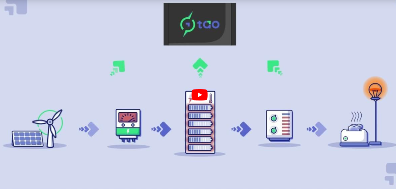
Accroît l'autonomie énergétiques
Supervise les cycles de charge et de consommation afin d'optimiser l'autonomie énergétique des utilisateurs tout en s'adaptant à leurs besoins en électricité.